Fasteners workbench based on screw-maker

Have some feature requests, feedback, cool stuff to share, or want to know where FreeCAD is going? This is the place.
Forum rules
Be nice to others! Read the FreeCAD code of conduct!
User avatar
KurtF
Posts: 161
Joined: Fri Mar 04, 2022 7:36 pm
Location: North Carolina, US
Contact:

Re: Fasteners workbench based on screw-maker

Post by KurtF »

When I wrote that above, esp. the "proposal to add thread functionality from my ThreadMaker tool into Fasteners Workbench" part, I didn't realize I was suggesting that Shai take on a full-blown dev. project. As if he could just plug a sketch-based, complex, parametric solid into this workbench. I can see now why he never replied. :-)

But I'm now half way through turning ThreadMaker into a macro. I have the External Thread Shaft nearly done (Int Thread Insert up next) and past prelim. testing. Once I have this properly codified in macro form, then it will be much more trivial to add to this workbench, should you and the user community want to.

It turns out Python is pretty easy to learn, if you already know Java. It's like a cross between Java and Microsoft BASIC from 1985. Easy to read and faster to master. {
I do miss my curly braces though
}

Here is a preview demo of ThreadMaker features:
ThreadShaftMacro.jpg
ThreadShaftMacro.jpg (989.03 KiB) Viewed 2283 times

* Lamp base is a standard M10 x 1.0 thread. I plan to add a selection list to the dialog box populated with standard sizes from the ISO and NPT standard thread charts. Selecting one of these will populate the Dia. and Pitch of the dialog box, but still allow custom length, taper, left-handed, and clearance.
* Lamp post is a left-handed thread. I last used this feature to print a twin-screw shaft which opened and closed clamping jaws when rotated.
* Lamp shade has a 10 degree taper (much larger than NPT allows) and 0.25mm pitch. It took 5 full seconds to build/render on my 5GHz 6-core CPU.
* Dialog box ISO and NPT buttons populate the Taper Angle box. Dialog box also pre-validates all data entries and prompts to correct. Designed to be easy to use without the mouse. Not done yet is pre-populating the dialog box with it's last-used values whenever it's opened.
* Min. cost to generate a threaded shaft: 1 mouse click (macro or wb icon) + 3 data entries (Length, tab, Pitch, tab, Diameter, enter).
* Not done yet is wiring up the thread body's properties into the finished object, so they will be available to edit like any other FC object props.
* Int Thread Inserts will have all the functionality of these Ext Thread Shafts.

Now, Shai... is THIS something you might be interested in adding to Fastener's? If not, that's OK. I'll be perfectly happy keeping it in macro form too.
Last edited by KurtF on Thu May 05, 2022 6:30 pm, edited 1 time in total.
May whatever Higher Power you believe in bless the Ukrainians. They are a decent people who never hurt anybody.
User avatar
shaise
Posts: 486
Joined: Thu Jun 11, 2015 8:11 am

Re: Fasteners workbench based on screw-maker

Post by shaise »

Hi Kurt,

Sorry for not replying til now, but I do follow the thread.
I am quite busy these days so I have less time to code for FreeCad, most of code lately was done by other very fine contributes.
I definitely agree your code can be a great feature to add to FW. As I see it it should be a new button in the threaded rods group that is marked as "custom thread maker". and of course it should be parametric - meaning able to be selected and adjusted after it was made.
If you can do it and make a pull request I'll be glad to add it. If not, I'll try to add it as soon as I have some spare time.

Thanks!
shai


the
User avatar
KurtF
Posts: 161
Joined: Fri Mar 04, 2022 7:36 pm
Location: North Carolina, US
Contact:

Re: Fasteners workbench based on screw-maker

Post by KurtF »

Awesome. Then I will start following the guidance for integration into Fasteners. That seems to be pretty well documented. I believe I'm a week or two away from having my code all tweaked out, so that will keep me busy too. My design will have 2 buttons I'd like to add to Fasteners: Thread Shaft (external) and Thread Insert (internal).

This is a fun code project, for a rusty, old developer. I've been using my own ThreadMaker design side x side with Fasteners for 3D printing, and it will be great to have all that functionality in one place.

Thanks, Shai. I'll pop back in here in a week or two when I have my ship together. :-)
May whatever Higher Power you believe in bless the Ukrainians. They are a decent people who never hurt anybody.
User avatar
Kunda1
Veteran
Posts: 13434
Joined: Thu Jan 05, 2017 9:03 pm

Re: Fasteners workbench based on screw-maker

Post by Kunda1 »

Very exciting stuff happening here. :D
Alone you go faster. Together we go farther
Please mark thread [Solved]
Want to contribute back to FC? Checkout:
'good first issues' | Open TODOs and FIXMEs | How to Help FreeCAD | How to report Bugs
kisolre
Veteran
Posts: 4166
Joined: Wed Nov 21, 2018 1:13 pm

Re: Fasteners workbench based on screw-maker

Post by kisolre »

Now is someone adds proper real clearances/tolerances that would be amazing :)
https://forum.freecadweb.org/viewtopic. ... 20#p593337
User avatar
KurtF
Posts: 161
Joined: Fri Mar 04, 2022 7:36 pm
Location: North Carolina, US
Contact:

Re: Fasteners workbench based on screw-maker

Post by KurtF »

kisolre wrote: Thu May 05, 2022 7:38 pm Now is someone adds proper real clearances/tolerances that would be amazing
I checked on this in Fasteners, and verified it actually created the specified clearance. Fasteners applies clearance as a global property for all it's various objects. The ThreadShaft/Insert tool I'm making applies clearance per-object. Either way, clearance results in radial shift of the thread surface inward on ext threads, and outward on int threads, creating the gap shown in white on the diagram you linked in your post.

Is this not correct? Your link to a thread diagram didn't suggest otherwise.
May whatever Higher Power you believe in bless the Ukrainians. They are a decent people who never hurt anybody.
kisolre
Veteran
Posts: 4166
Joined: Wed Nov 21, 2018 1:13 pm

Re: Fasteners workbench based on screw-maker

Post by kisolre »

KurtF wrote: Thu May 05, 2022 9:48 pm I checked on this in Fasteners, and verified it actually created the specified clearance.
Check my examples here and here. There is NO clearance. Still valid with the latest Fasteners WB(0.3.41). 3D printer compensation is NOT clearance. Its purpose is to create a smaller/bigger model, which when 3D printed will result in bigger/smaller object with proper desired dimensions. If there was clearance then the Standard thread generation should result in threads within that black regions of the diagram.
User avatar
KurtF
Posts: 161
Joined: Fri Mar 04, 2022 7:36 pm
Location: North Carolina, US
Contact:

Re: Fasteners workbench based on screw-maker

Post by KurtF »

kisolre wrote: Fri May 06, 2022 5:24 pm Check my examples here and here. There is NO clearance
I did. Sorry, but there's nothing in your examples to show that you were setting clearance correctly in the FW properties. Your 2nd example seems to show that you are trying to achieve the clearance using the offset property, which isn't gonna apply clearance to FW threads. I didn't personally test the die and tap objects, but I did test it on various other FW nuts and bolts and it worked as documented.

kisolre wrote: Fri May 06, 2022 5:24 pm 3D printer compensation is NOT clearance.
I disagree. Thread clearance is exactly the kind of compensation I need as a 3D thread printer.

Do we agree on the basic definition: Thread clearance is applied radially only (not in thread Z axis), and generates a gap between mating threads, as shown by the white area on your diagram?

Variance is allowed in the thread spec standards, which specify both min and max on each diameter. This is represented by the black area of your diagram.

Variance is allowable deviation within a diameter; Clearance is added to or subtracted from the diameter to force a gap.
May whatever Higher Power you believe in bless the Ukrainians. They are a decent people who never hurt anybody.
User avatar
KurtF
Posts: 161
Joined: Fri Mar 04, 2022 7:36 pm
Location: North Carolina, US
Contact:

Re: Fasteners workbench based on screw-maker

Post by KurtF »

FWTapDieClearance.jpg
FWTapDieClearance.jpg (809.11 KiB) Viewed 1894 times
The Standard Measure tool isn't very precise, but I was shooting for 0.2mm on that. I think FW worked fine here.

Code: Select all

OS: Windows 10 (10.0)
Word size of FreeCAD: 64-bit
Version: 0.20.28774 (Git)
Build type: Release
Python 3.8.13, Qt 5.12.9, Coin 4.0.0, OCC 7.5.3
Locale: English/United States (en_US)
Installed mods: 
  * fasteners 0.3.40
May whatever Higher Power you believe in bless the Ukrainians. They are a decent people who never hurt anybody.
kisolre
Veteran
Posts: 4166
Joined: Wed Nov 21, 2018 1:13 pm

Re: Fasteners workbench based on screw-maker

Post by kisolre »

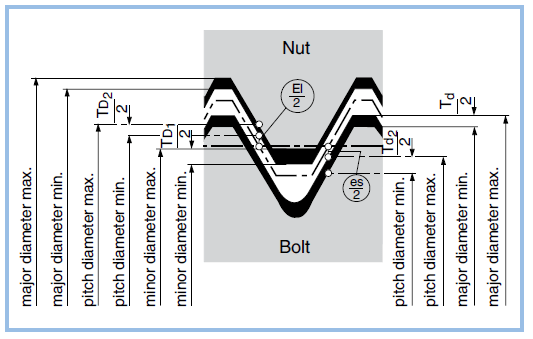
Not to jump between threads so much here is the image in question:
Image from the article.
KurtF wrote: Fri May 06, 2022 6:04 pm Thread clearance is exactly the kind of compensation
Clearance is not a compensation. Clearance is the result of actual manufacturing of the object within desired tolerances. So if you want to machine a bolt its outside diameter should be between Bolt/Major diameter min and Bolt/Major diameter max. From the PDF there:
Screws tolerance.JPG
Screws tolerance.JPG (104.82 KiB) Viewed 1881 times
the M8 screw should have actually 7.972mm OD max. Fasteners should produce this size as standard. And then if you are going to 3D print it you apply 3D printing compensation so hopefully the resulting 3D printed thread will have 7.972 mm OD and not 8.0mm. That OD should give the proper clearance to any nut manufactured elsewhere to be able to screw on that 3D printed thread.
When I print matching threads I directly make one of the threads the offset I suspect will work. Like for M24 (24x3) I make the female thread M24 but the male one custom 23.6x3 (2x0.2mm designed clearance which would hopefully result in actual 2x0.005). If an actual machined thread will be used in the 3D printed one I make the 3D printed one as standard and then use tap/die to calibrate the size.
Post Reply