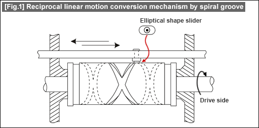
I need 0.5 stroke per revolution (or even less) that's mean with one (or more) revolution(s) the stroke goes down and with the second (best would be with a different value) revolution(s) it goes up.
The macro does not accept decimal numbers, I wonder if it's by design or there is a technical limitation to that.
I've tried to change line #87 from `getInt()` to `getDouble()` and using 0.5 as stroke per revolution parameter no errors are thrown even the resulting geometry seems the same as 1. Instead I was expecting a full revolution downwards and another upwards (of course they intersect at the middle point). Something like this:

I tried this workaround:
1. run the macro with 1 as revolutions per stroke parameter
2. duplicate the GrooveFeature
3. rotate on z-axis one of the two of 180 °
4. make an union of both
5. cut the union from the cylinder
It seems correct:
The best would be allowing the generation of multiple revolutions for stroke (or accepting decimal numbers with the current definition). I gave a look at the code:
Code: Select all
def makeBSpline(strokesPerRevolution,strokeFactor,radius,steps):
    a = strokesPerRevolution
    b = strokeFactor
    c = radius
    interval = (2*math.pi)/float(steps)
    points=[]
    t = 0.0
    maxT = 2*math.pi
    counter=0
    while t <= maxT:
        say(u'Step '+str(counter)+u' of '+str(steps)+u'\n')
        counter +=1
        processEvents()
        x = math.cos(t)*c
        y = math.sin(t)*c
        z = math.sin(t*a/2.0)*math.cos(t*a/2.0)*c*b
        points.append(App.Vector(x,y,z))
        t += interval

    Draft.makeBSpline(points,closed=True,face=False)
    say(u'Done with BSpline\n')
    processEvents()
Code: Select all
z = math.sin(t*a/2.0)*math.cos(t*a/2.0)*c*b
I'm aware it's off-topic, but I'm sure you guys have a lot of experience here. So I would thank you if you wouldn't mind to give me an advice.
What if the load offers some resistance? When crossing the intersection, if the load exerts a force in the opposite way of the current direction of the stroke, how to avoid the pin to slide inside the wrong path?
