If you're new to Path workbench, either as a user or as a developer, the following links may prove helpful
Developing for Path
Path Coding Style Guide
Standard Test Shapes
Learning the Path Workbench
Using FreeCAD Path Video Playlist
Scripting for Path Workbench
History and Background
Shared Design Document
Dan's writeup on how HeeksCNC does toolpath generation
Sliptonic's writeup on HeeksCNC post-processing
Links and Background
Forum rules
Be nice to others! Respect the FreeCAD code of conduct!
Be nice to others! Respect the FreeCAD code of conduct!
-
sliptonic

- Veteran
- Posts: 3459
- Joined: Tue Oct 25, 2011 10:46 pm
- Location: Columbia, Missouri
- Contact:
Links and Background
Last edited by sliptonic on Fri Mar 02, 2018 8:08 pm, edited 3 times in total.
Re: Links and Background
A note on my existing 3D CAM-algorithms in OpenCAMLib, c++ code with python bindings, under GPL license.
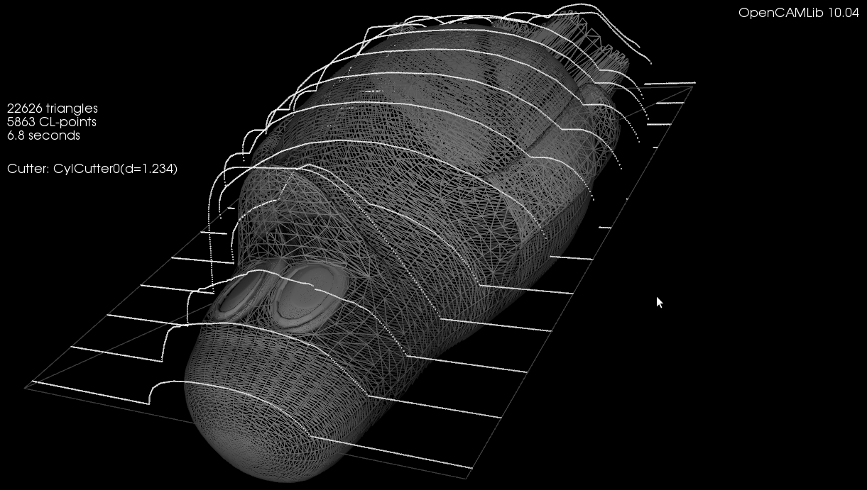
Typical "drop-cutter" ("axial tool projection") finish toolpath.
http://www.anderswallin.net/wp-content/ ... 4/tux1.png
These may essentially be any toolpath in the XY plane which is the "dropped" or "projected" down onto an STL surface to produce cutter-location points. There is a filter for reducing the number of points on straight parts of the surface. A filter for recognizing circular arcs in the principal planes (i.e. g2/3 moves) would be a good addition.
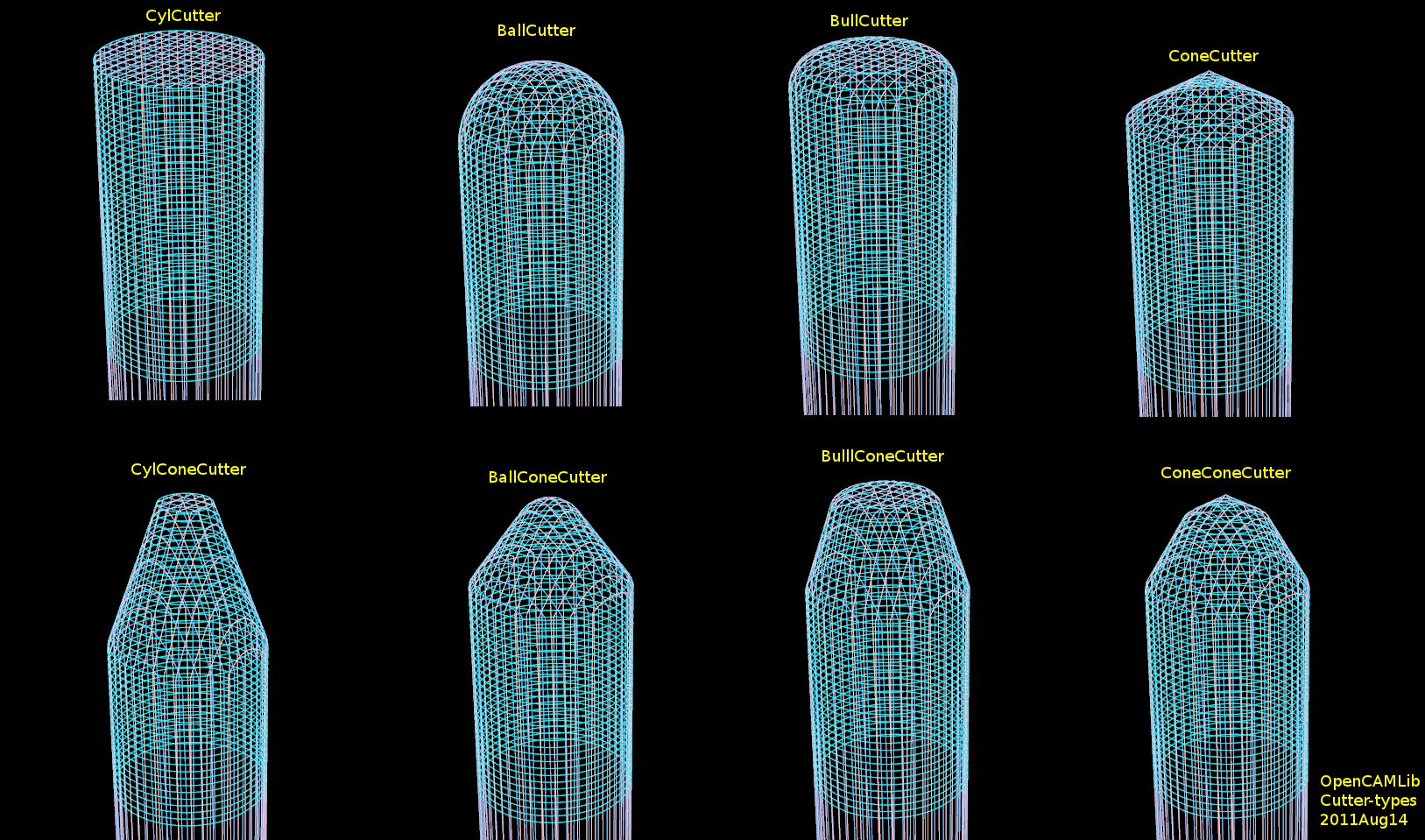
Drop-cutter works with the following tool-shapes. The bottom row shows composite-cutters that are combinations of the top-row basic cutter shapes. Many more of these are possible to define, if desired.
http://www.anderswallin.net/wp-content/ ... 8/all1.jpg
A stock-to-leave feature is implemented thorugh offset cutters. When we want to machine a surface with a positive stock-to-leave value we first offset the cutter outward, calculate the toolpath with this larger-than-actual cutter, and then machine with the small original cutter. This should result in the desired surface with the given stock-to-leave.
(I seem to have no good image of this idea in my blog, sorry...)
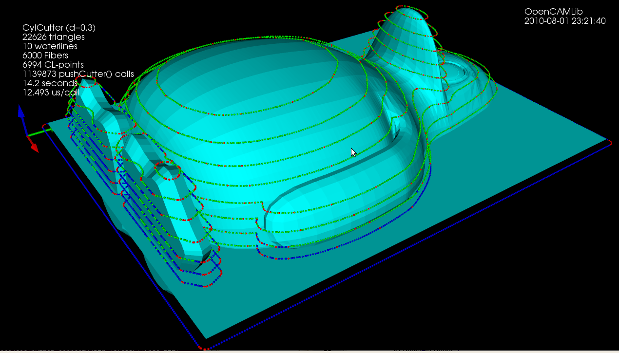
A cutter can also be "pushed" in the XY plane ("radial tool projection"). When these cutter-location points are hooked up correctly we have a waterline toolpath:
http://www.anderswallin.net/wp-content/ ... e_tux1.png
There are still issues with how the cutter-location points should validly be hooked up into a waterline-loop. Your patches will be welcome!
The typical roughing-strategy is to rough or clear-out "Z-terraces" where each terrace is defined by a waterline and the stock-definition. For a 3D roughing operation these waterlines calculated in 3D are thus input for a 2D roughing/clearing algorithms that is run at each Z-step.
TODO/Plans:
- Pencil-milling. By looking at the cutter-contact point with a rounded tool (BallCutter or BullCutter) it is possible to determine the surface normal at the point where we make contact with the model. Pencil-milling cutter-locations are points on the STL model where this contact-normal changes abruptly. It should be straightforward to create a mesh in the XY-plane covering the whole model, then run drop-cutter on all vertices in the mesh, then find places where the cutter-normal changes abruptly. Optionally refine the mesh adaptively in interesting regions. Then hook up these found points into pencil-milling paths.
- Constant-scallop. Again start with a mesh in the XY-plane covering the whole model. Run drop-cutter on this to project "wrap" the mesh down on the model. Refine adaptively to desired accuracy. Now run a "geodesic distance field" or similar (many papers/descriptions exist) algorithm on this mesh. This results in equally-spaced curves on the mesh, which at least with BallCutter will be exactly (or an approximation(?)) a constant-scallop toolpath. See for example this image: http://www.graphics.rwth-aachen.de/medi ... c076c1.png
- non-simultaneous 4/5-axis paths are possible, i.e. toolpaths where we do not machine while the 4/5 axis rotates are essentially just 3-axis paths, but with the STL model oriented/rotated into a new position. Applying all existing 3-axis oprations to rotated STL-model should be straightforward.
My conclusion is that on the geometry/math side of things there's already a bit of work done! It's mainly the integration part into freecad that is lacking now.
Anders
Typical "drop-cutter" ("axial tool projection") finish toolpath.
http://www.anderswallin.net/wp-content/ ... 4/tux1.png
These may essentially be any toolpath in the XY plane which is the "dropped" or "projected" down onto an STL surface to produce cutter-location points. There is a filter for reducing the number of points on straight parts of the surface. A filter for recognizing circular arcs in the principal planes (i.e. g2/3 moves) would be a good addition.
Drop-cutter works with the following tool-shapes. The bottom row shows composite-cutters that are combinations of the top-row basic cutter shapes. Many more of these are possible to define, if desired.
http://www.anderswallin.net/wp-content/ ... 8/all1.jpg
A stock-to-leave feature is implemented thorugh offset cutters. When we want to machine a surface with a positive stock-to-leave value we first offset the cutter outward, calculate the toolpath with this larger-than-actual cutter, and then machine with the small original cutter. This should result in the desired surface with the given stock-to-leave.
(I seem to have no good image of this idea in my blog, sorry...)
A cutter can also be "pushed" in the XY plane ("radial tool projection"). When these cutter-location points are hooked up correctly we have a waterline toolpath:
http://www.anderswallin.net/wp-content/ ... e_tux1.png
There are still issues with how the cutter-location points should validly be hooked up into a waterline-loop. Your patches will be welcome!
The typical roughing-strategy is to rough or clear-out "Z-terraces" where each terrace is defined by a waterline and the stock-definition. For a 3D roughing operation these waterlines calculated in 3D are thus input for a 2D roughing/clearing algorithms that is run at each Z-step.
TODO/Plans:
- Pencil-milling. By looking at the cutter-contact point with a rounded tool (BallCutter or BullCutter) it is possible to determine the surface normal at the point where we make contact with the model. Pencil-milling cutter-locations are points on the STL model where this contact-normal changes abruptly. It should be straightforward to create a mesh in the XY-plane covering the whole model, then run drop-cutter on all vertices in the mesh, then find places where the cutter-normal changes abruptly. Optionally refine the mesh adaptively in interesting regions. Then hook up these found points into pencil-milling paths.
- Constant-scallop. Again start with a mesh in the XY-plane covering the whole model. Run drop-cutter on this to project "wrap" the mesh down on the model. Refine adaptively to desired accuracy. Now run a "geodesic distance field" or similar (many papers/descriptions exist) algorithm on this mesh. This results in equally-spaced curves on the mesh, which at least with BallCutter will be exactly (or an approximation(?)) a constant-scallop toolpath. See for example this image: http://www.graphics.rwth-aachen.de/medi ... c076c1.png
- non-simultaneous 4/5-axis paths are possible, i.e. toolpaths where we do not machine while the 4/5 axis rotates are essentially just 3-axis paths, but with the STL model oriented/rotated into a new position. Applying all existing 3-axis oprations to rotated STL-model should be straightforward.
My conclusion is that on the geometry/math side of things there's already a bit of work done! It's mainly the integration part into freecad that is lacking now.
Anders
Re: Links and Background
And now a note on my 2D library, OpenVoronoi, also c++ code with python bindings, under GPL license.
The voronoi-diagram is essentially a proximity-map, dividing the plane into regions where the interior of each region "belongs" to a certain input-geometry object because points in this region are closer to the input-object than to any other object.
Voronoi diagrams (or their dual, Delaunay triangulations) have many uses in computational geometry.
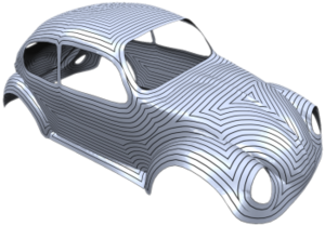
An obvious use is the generation of 2D offsets:
https://picasaweb.google.com/1061886054 ... 8267087346
It is obviously possible to also produce "Profiling" toolpaths where we only have an input profile, not a closed polygon. I have not looked at this yet, but it should be straightforward.
Another one is the medial-axis, loosely defined as the points interior to a geometry which are as far as possible from the boundaries of the input geometry:
https://picasaweb.google.com/1061886054 ... 0471914946
These can be used for V-carving: http://www.youtube.com/watch?v=n4P9SvT4L7g
A more interesting development is "smart" pocketing where the idea is to guarantee that the tool does not cut into the material exessively (such as it does with conventional offset or zigzag pocketing strategies). This is still under development but shows some promise:
http://www.youtube.com/watch?v=lfIU_gv0iB8
Notes:
- A polygon library (libarea, clipper, kbool) will usually not take circular arcs as input. Circular arcs must be approximated with many short line-segments for these libraries. A voronoi-diagram algorithm that supports circular arcs does not have this limitation. Both types of libraries can produce circular arcs in the output (e.g. offsets).
- An alternative to OpenVoronoi is Boost.Polygon.Voronoi (Boost license) which is not officially part of Boost yet, but shows some promise. My benchmarks indicate it is currently faster than OpenVoronoi.
- Neither OpenVoronoi nor Boost.Polygon.Voronoi support circular arc input currently, but support is planned.
- There's also a voronoi algorithm in CGAL, but everyone seems to agree it is slow and buggy.
have fun,
Anders
The voronoi-diagram is essentially a proximity-map, dividing the plane into regions where the interior of each region "belongs" to a certain input-geometry object because points in this region are closer to the input-object than to any other object.
Voronoi diagrams (or their dual, Delaunay triangulations) have many uses in computational geometry.
An obvious use is the generation of 2D offsets:
https://picasaweb.google.com/1061886054 ... 8267087346
It is obviously possible to also produce "Profiling" toolpaths where we only have an input profile, not a closed polygon. I have not looked at this yet, but it should be straightforward.
Another one is the medial-axis, loosely defined as the points interior to a geometry which are as far as possible from the boundaries of the input geometry:
https://picasaweb.google.com/1061886054 ... 0471914946
These can be used for V-carving: http://www.youtube.com/watch?v=n4P9SvT4L7g
A more interesting development is "smart" pocketing where the idea is to guarantee that the tool does not cut into the material exessively (such as it does with conventional offset or zigzag pocketing strategies). This is still under development but shows some promise:
http://www.youtube.com/watch?v=lfIU_gv0iB8
Notes:
- A polygon library (libarea, clipper, kbool) will usually not take circular arcs as input. Circular arcs must be approximated with many short line-segments for these libraries. A voronoi-diagram algorithm that supports circular arcs does not have this limitation. Both types of libraries can produce circular arcs in the output (e.g. offsets).
- An alternative to OpenVoronoi is Boost.Polygon.Voronoi (Boost license) which is not officially part of Boost yet, but shows some promise. My benchmarks indicate it is currently faster than OpenVoronoi.
- Neither OpenVoronoi nor Boost.Polygon.Voronoi support circular arc input currently, but support is planned.
- There's also a voronoi algorithm in CGAL, but everyone seems to agree it is slow and buggy.
have fun,
Anders
-
sliptonic
- Veteran
- Posts: 3459
- Joined: Tue Oct 25, 2011 10:46 pm
- Location: Columbia, Missouri
- Contact:
Re: Links and Background
An update: As of August 2018 both Openvoronoi and OpenCamLib are licensed LGPL
Re: Links and Background
That's good news! Some time ago I had a look at the docs of opencamlib. There seems to exist already code for different forms of mills. Perhaps we can reuse it.
A Sketcher Lecture with in-depth information is available in English, auf Deutsch, en français, en español.
-
RatonLaveur
- Posts: 991
- Joined: Wed Mar 27, 2019 10:45 am
Re: Links and Background
Here is a reddit list of many deprecated and recent opensource software for CNC and CAM. It seems the list has been steadily updated starting about a year ago with posters comments.
https://www.reddit.com/r/CNC/comments/a ... =post_body
Of notable interest maybe the Nesting tools or some Plasma cutter oriented pieces of software. Perhaps this will already be known to the PathWB gurus...perhaps it will inspire. Hopefully there are things in there that may be of use from a purely functional/license point of view.
Also...FreeCAD PathWB is mentioned